

 The Build Process begins with an idea. Your idea. A custom bolt action rifle is custom only to you, so every detail needs to be thought out carefully. The purpose, style, and feel of the rifle are all things that must be considered when planning a build. This is when the caliber, barrel length, and stock are selected. After this, the fine details such as bolt options, trigger, magazines, finish, and sighting systems are sorted out. Before any work begins, every aspect of your custom bolt action rifle has been selected by you, the shooter, to meet whatever your needs may be. During this time, I am here to answer any questions and make recommendations based off my experiences.
The Build Begins
After planning is complete and a down payment of 50% has been received, the parts for your custom bolt-action rifle are ordered. The lead-time varies based on the availability of parts. A typical lead-time is approximately 3-6 months. Once all of the parts arrive, machining can begin.
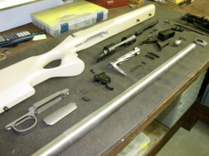
The following slide show is to give you an idea of what exactly goes into building a custom bolt-action rifle. It is not meant to be an instructional presentation for the at home do-it-yourselfers. There may be any number of ways to achieve the same goal, this is simply my way, I believe this to be the best way to assure accuracy in a rifle.
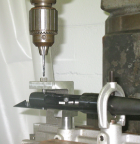 I first begin by opening the existing 6-48 screw holes in the receiver, (for the scope base,) to accept 8-40 screws. I do this to increase the holding power of the screws to the action. I do not want anything coming loose in the field, and this assures that the base will remain solid. The scope base is the foundation for the scope itself, any movement of the base and accuracy is lost.
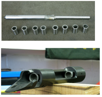 Next I will ream the bolt body raceway to .705”. This will be the foundation of the blueprinting process. All clean-up cuts to the receiver threads, bolt lug recesses, and receiver face will be determined here. I use a special set of bushings and a special receiver reamer to accomplish this. I insert the correct bushings, front and rear, and then slowly ream the bolt body raceway. This removes only a couple of thousandths of an inch, which is enough to perfectly align the bolt with the axis of the bore.
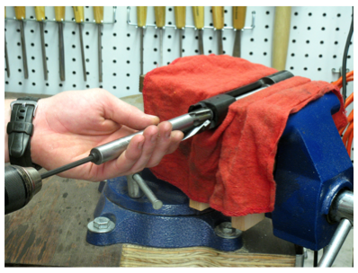 Reaming the bolt body raceway.
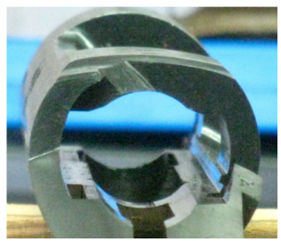 Bolt body raceway opened to .705”
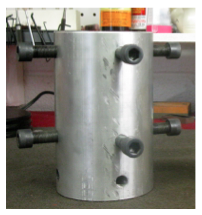 After the bolt body raceway has been reamed to .705”, the receiver can now be dialed in to within .0001” on the lathe. This is done using a special holding fixture. The reamer also serves as an indicator rod for dialing in. No cuts are made until the receiver is dialed in to within .0001”. Note: the numbers on the fixture coincide with the 4 sides of the receiver
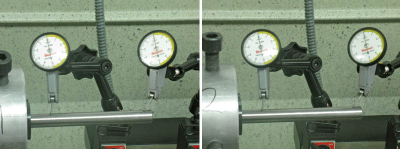
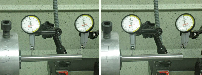
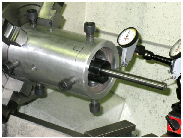 Here is another picture of the set-‐up.
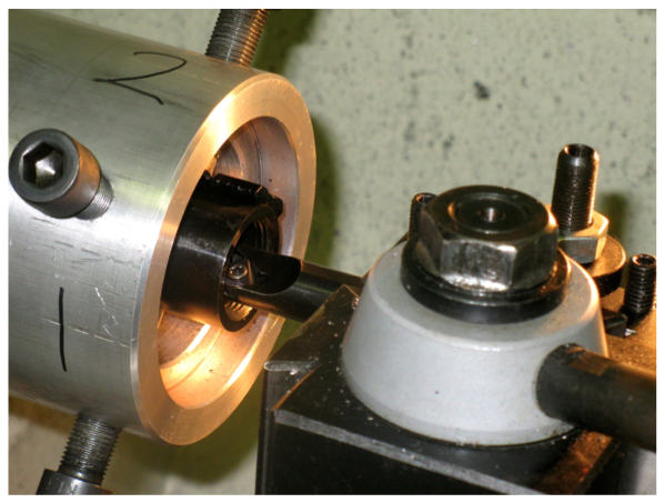 The existing threads are now cleaned up. Very light cuts are made during the entire process. If too heavy of a cut is made the set-‐up will be bumped out of alignment. The following pictures show the progression of the thread clean-‐up. The threads are only cut deep enough to ensure absolute uniformity, usually .002-‐.010”
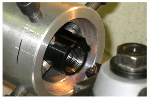 Notice the high and low spots of the existing threads, this is exactly what we want to remove.
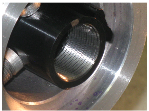 A picture of the threads after clean-‐up.
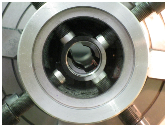 Now that the threads are cleaned up, the bolt lug recesses and receiver face still need to be faced off. This picture shows the bolt lug recesses trued, while only about half of the receiver face has been trued. Very light cuts are made. .0005” at a time, until everything is perfectly square.
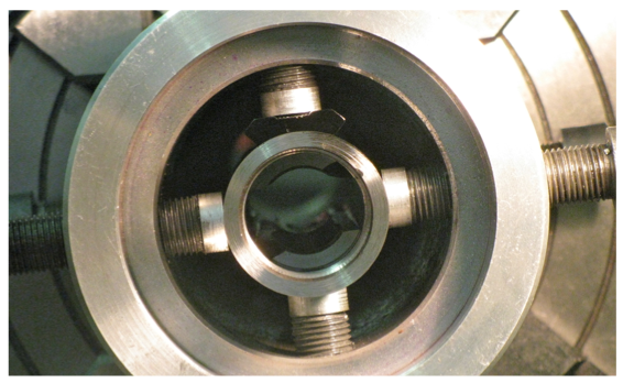 Almost there, still need to take another .0005”
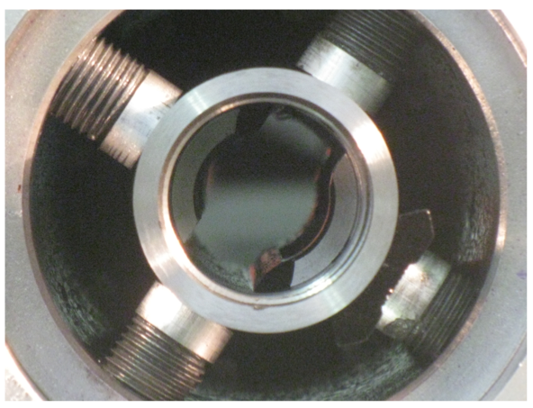
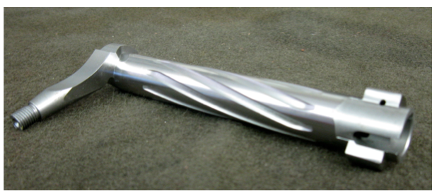 Now that the receiver is trued, it is time to begin work on the over-‐sized Pacific Tool and Gauge (PTG) bolt. These bolts can be ordered with many different options. I prefer one-‐ piece bolts with milled spiral fluting and a Sako style extractor cut. A straight or swept handle and the bolt knob are up to the shooter. I prefer something with some meat to it. The last thing you want to do is miss the bolt when you really need another round.
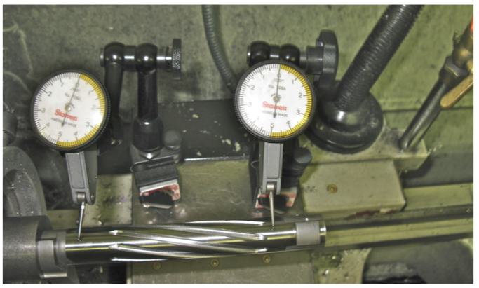 A special mandrel is threaded into the rear of the bolt and inserted into the same fixture used for dialing in the receiver. It is then dialed in to within .0001” in the same fashion as the receiver. A custom dead center is then inserted into the firing pin hole of the bolt. Then, and only then, are trueing cuts made. Very light (.0005”) trueing cuts are made on the bolt lugs and bolt face. PTG makes some of the finest components on the market, they probably don’t need to be trued at all, but for my peace of mind I make sure that everything is square.
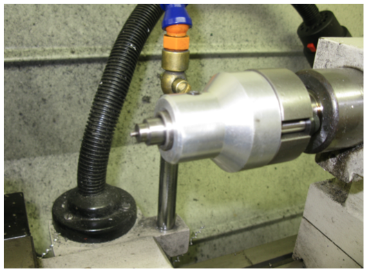 Custom dead center used for bolt trueing.
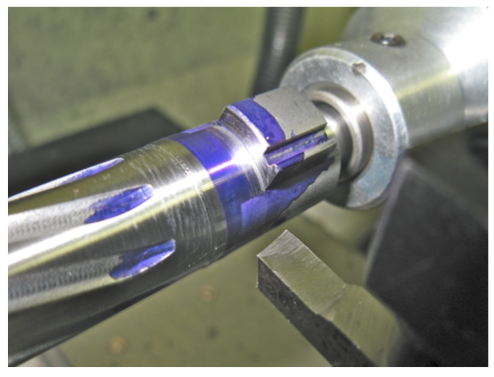 Very light (.0005”) cut being made on the bolt lugs.
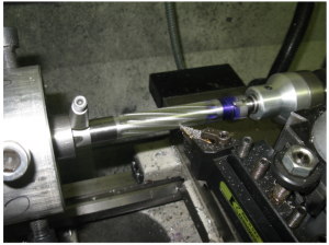 Once the lugs are trued, there is some work that must be done to the bolt body itself to ensure smooth operation upon completion. The bolt body is custom ordered with an outside diameter of .704”. This leaves .0005” of clearance within the now oversized .705” bolt body raceway. If the bolt body is left this tight, the action will be too sluggish and run the risk of binding. It also does not allow dirt or grit any place to go. So how do we achieve the best of both worlds? By turning the center of the bolt body down to near factory dimensions. This gives the benefits of a sleeved bolt, on a one-‐piece bolt body, a much cleaner look in my opinion. The outside diameter is left at .704” at the front and rear of the bolt body, where the bolt contacts the receiver during lockup.
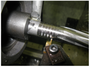 Next grooves are cut into the oversized areas of the bolt body to the same diameter as the center of the bolt body. Like I mentioned earlier, these bolts fit very tight into the receiver, the grooves are only there to allow dirt or grit a place to go.
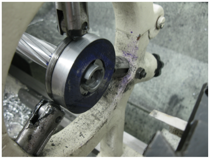 A special collar is now installed over the bolt lugs. Once the collar has been trued, a steady rest is mounted onto the lathe, using the collar as the resting point. Now the dead center can be removed to access the bolt face. Again, very light (.0005”) cuts are made to clean up the bolt face.
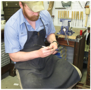 The machining on the bolt is now complete, but the fitting process is still not finished. As mentioned previously, the bolt-‐to-‐bolt body raceway fit is very tight even though the center of the bolt body has been relieved. Now, both surfaces of the bolt that are in contact with the receiver (during lockup,) are modified for smoother operation. To do this, these areas of the bolt are made elliptical in shape, (think oval,) so that while cycling the bolt there is plenty of clearance between the bolt body and the bolt body raceway ,yet during lockup, (while firing,) the fit is extremely tight. This is done by hand and is a very tedious process. The lines are first laid out using Dykem Blue, a square, and a scribe. The portion of the bolt not in contact with the receiver during lockup is then relieved with a fine-‐cut file and finished with a Cratex wheel in a Dremel. This results in a very tight fit during lockup and very smooth operation during cycling.
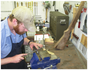 Hand filing the bolt body with a fine-‐cut file. This is very tedious and time consuming, but well worth the effort in the end.
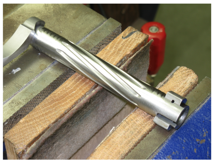 Here is a picture of the final fitting and shaping of the bolt. Notice the trued, grooved surfaces on the bolt directly behind the lugs. This is the portion in contact with the receiver during lockup. Notice the side nearest the camera (and opposite) have been relieved for smooth cycling.